


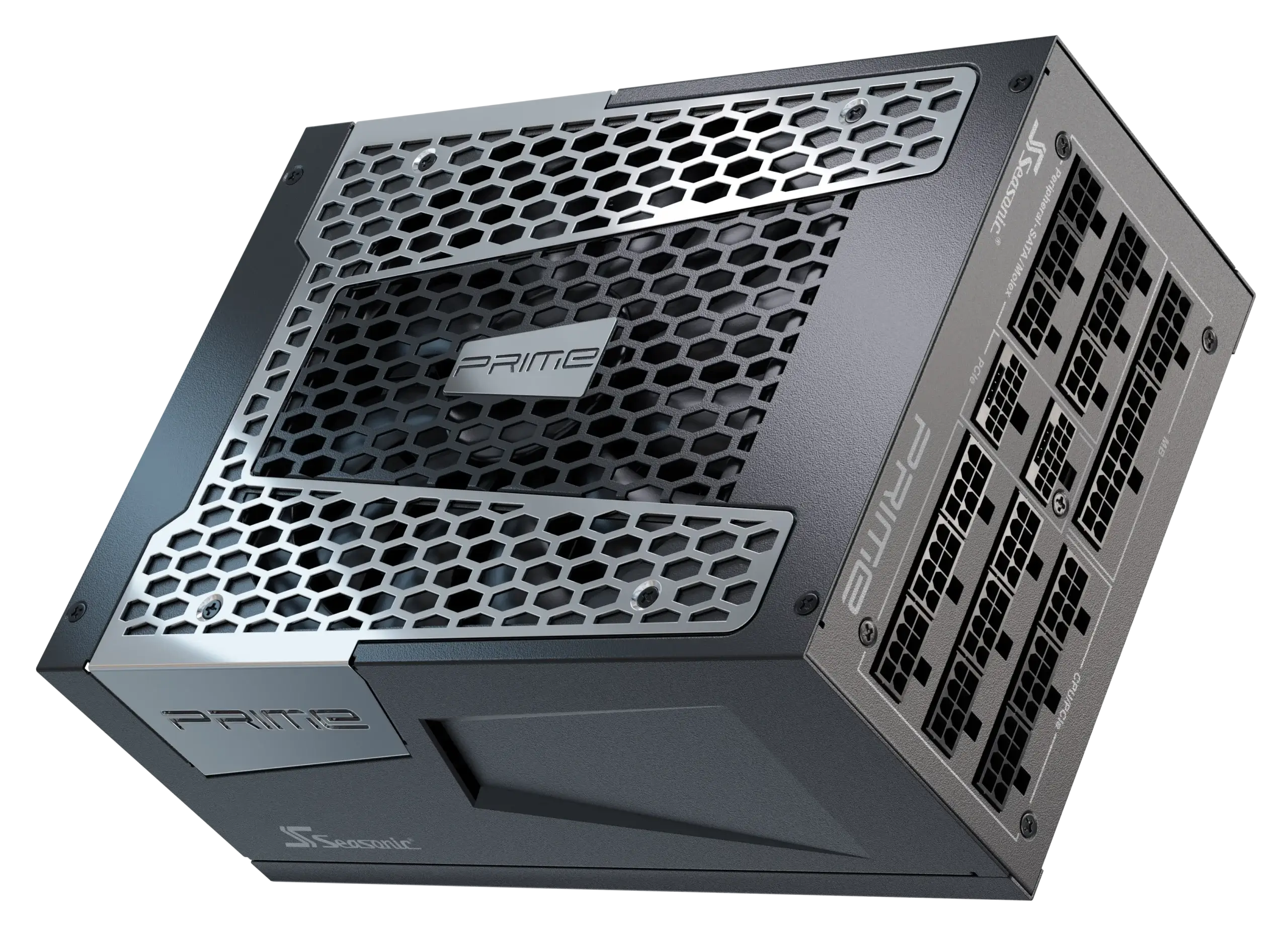
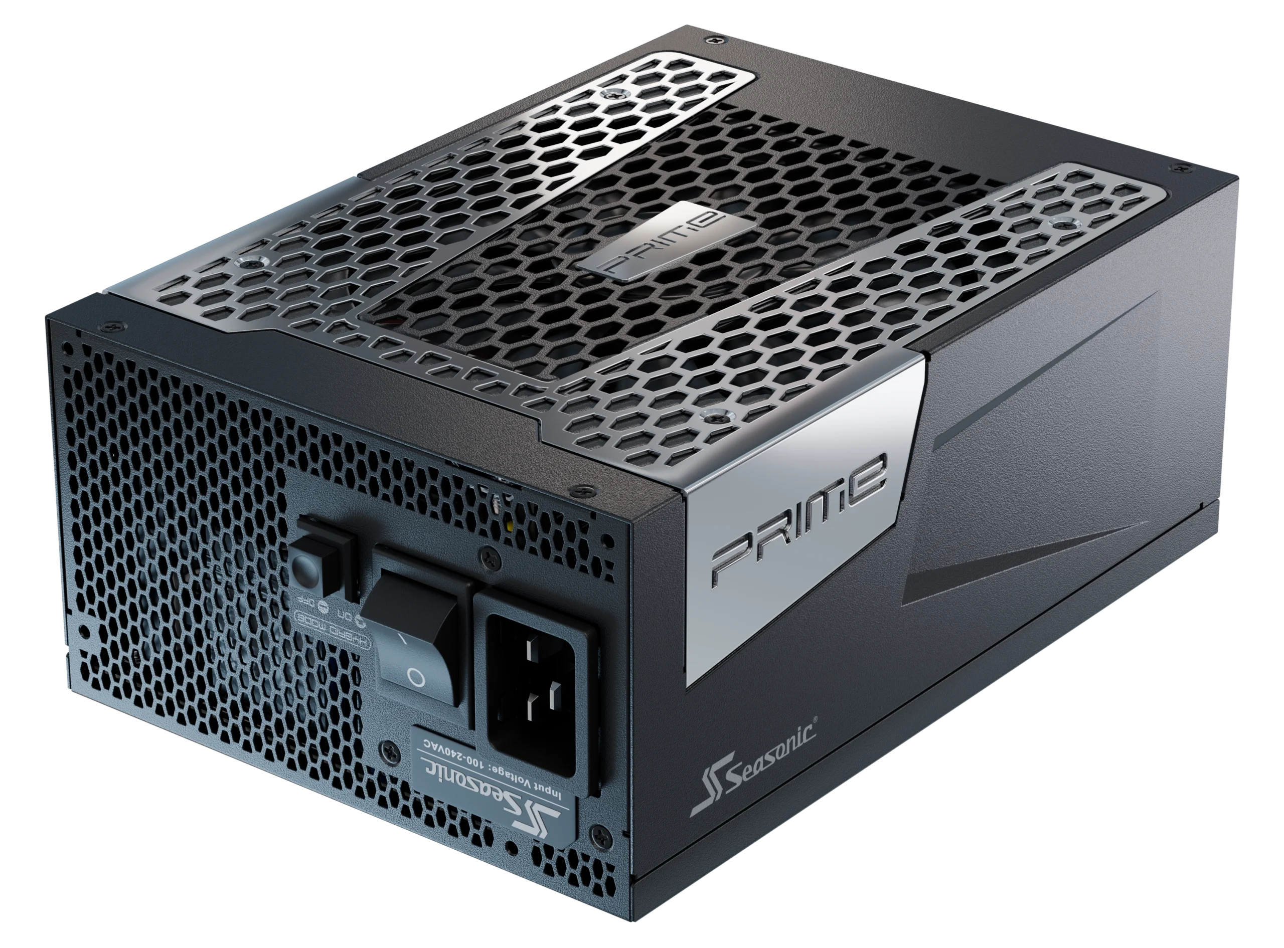
Seasonic PRIME TX Wins EHA 2026 Best PSU Series Award
The European Hardware Association (EHA) includes nine of the largest independent technology related review- and news sites across the continent, with a combined readership of more than 22 million technology enthusiasts, gamers, and influencers.

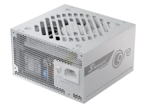
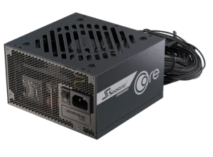
Seasonic CORE Wins EHA 2026 Best Value PSU Series Award
The CORE Series combines proven Seasonic reliability, modern ATX 3.1 support, and exceptional value—earning recognition from Europe’s leading hardware media.

Find Your PSU

Power Supplies
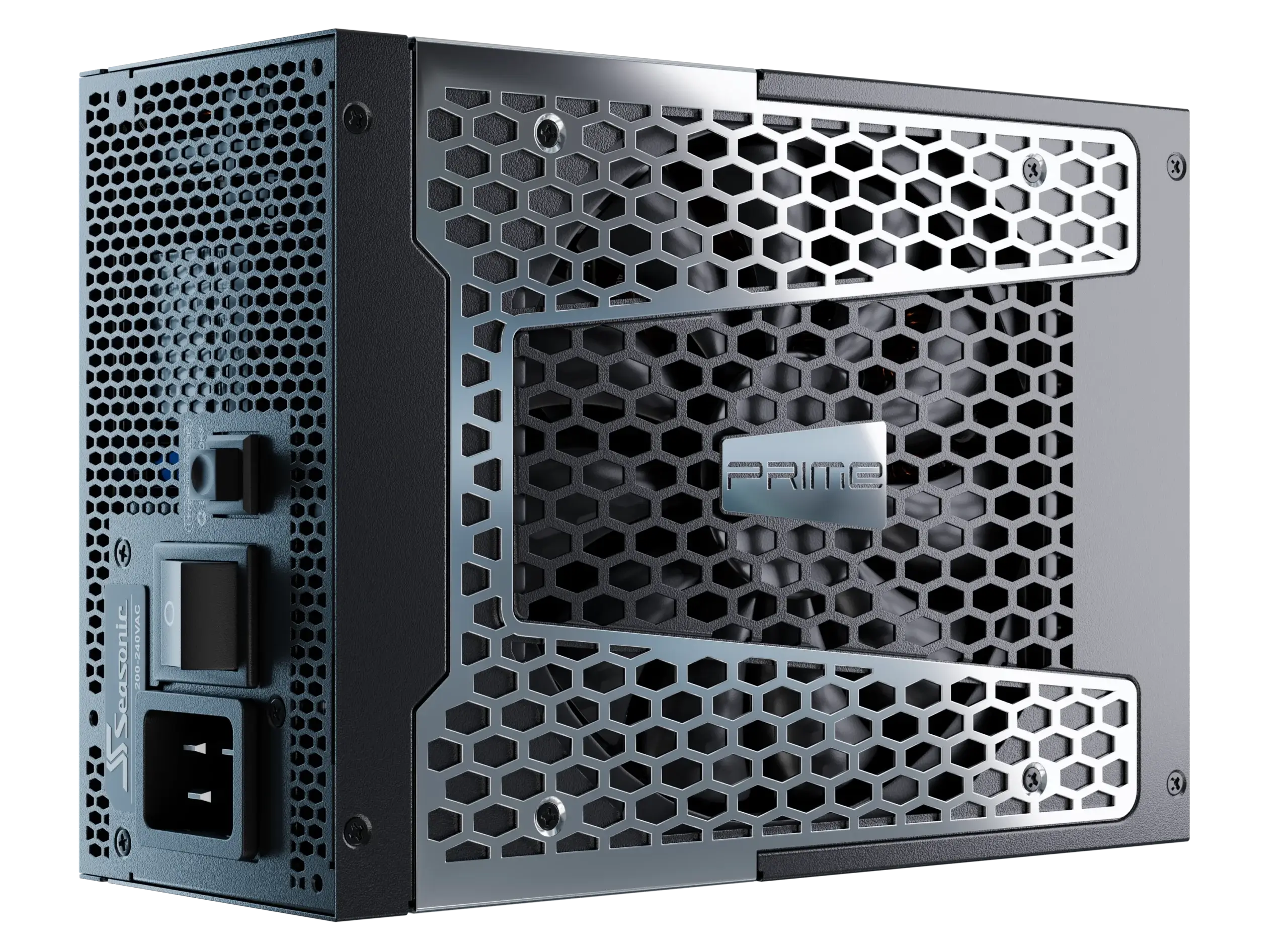
PRIME TX ATX 3.1 is the Best PSU 2026
The Seasonic PRIME TX 3.1 Series is built on top of all the great features of PRIME TX platform with added ATX 3.1.
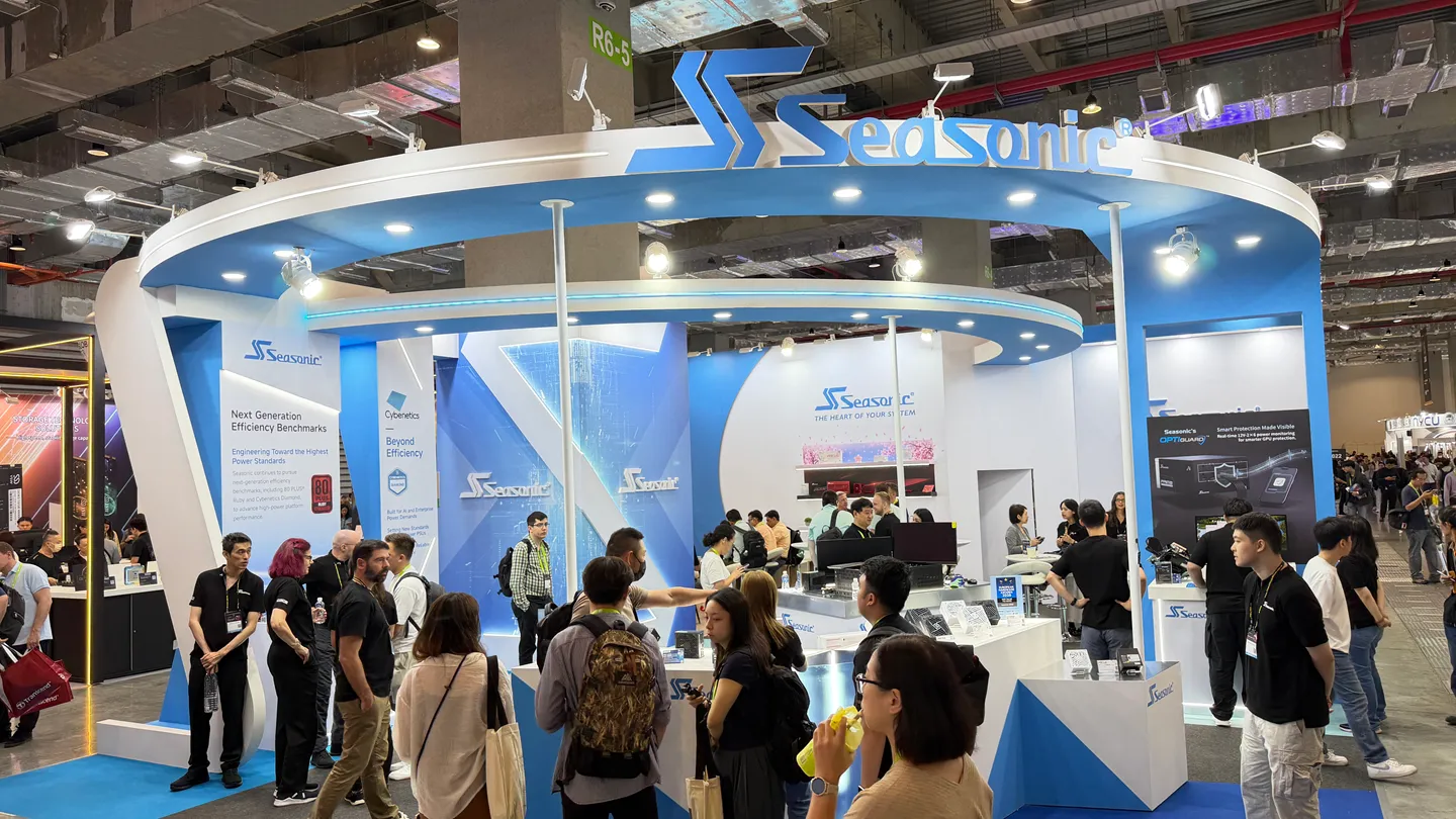
Seasonic at Computex 2026
Highlights from Taipei
Explore Seasonic Computex 2026 highlights, including next-generation PSU platforms, workstation power solutions, new product showcases, and the Seasonic Legacy Museum.
Accessories
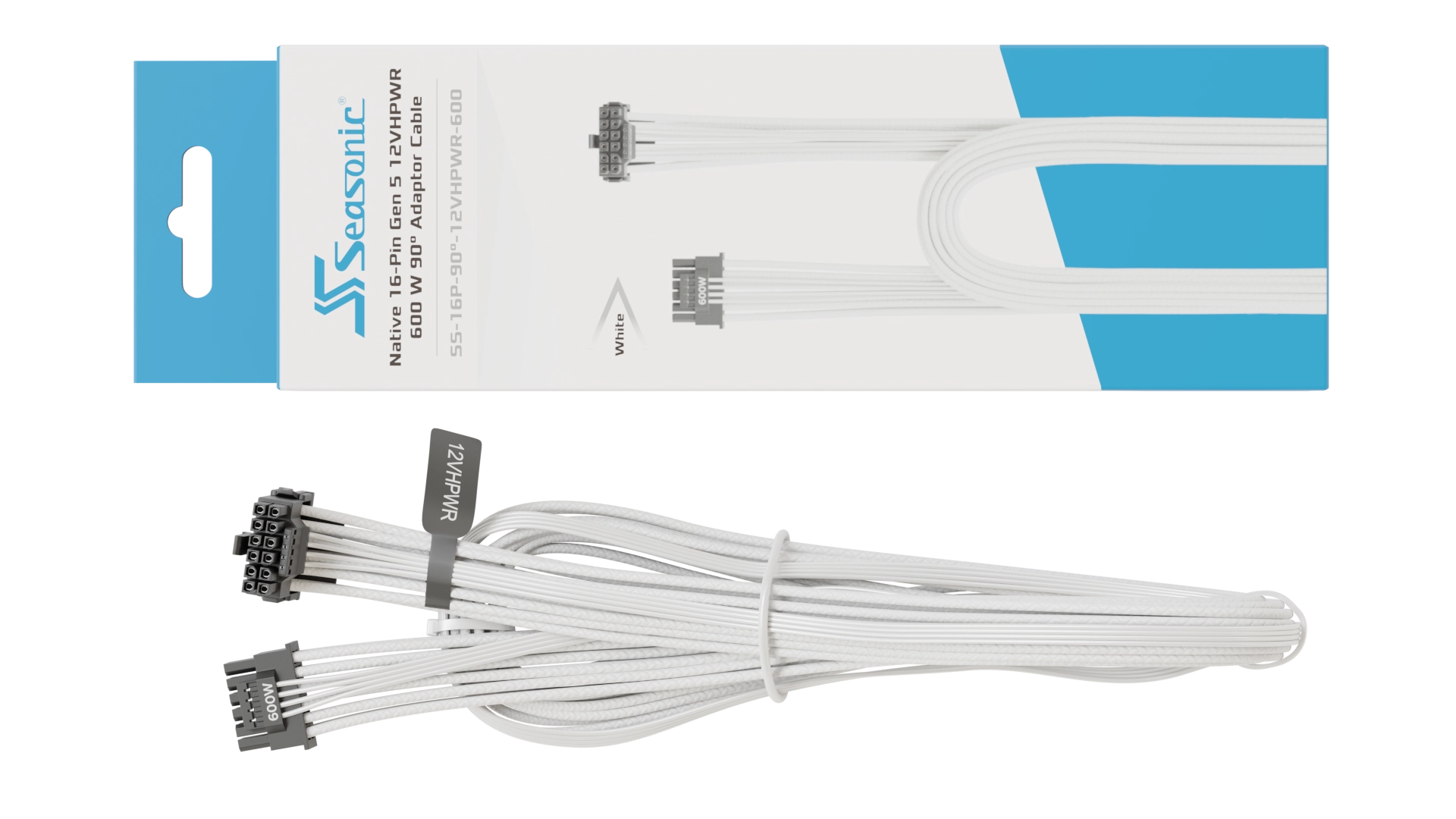
Seasonic Native 12VHPWR 90° Cable
Offering up to 600 W of power, the Seasonic native 12VHPWR 90-Degree cable has been crafted with high quality materials

Accessories
Seasonic Native 12V-2×6 Cable
A Single Connector To Power Them All
Power Supplies
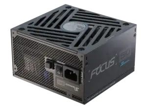
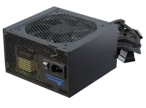
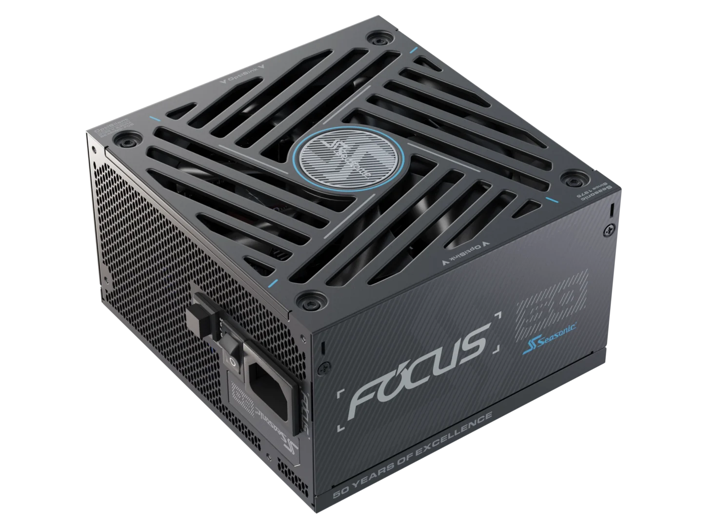
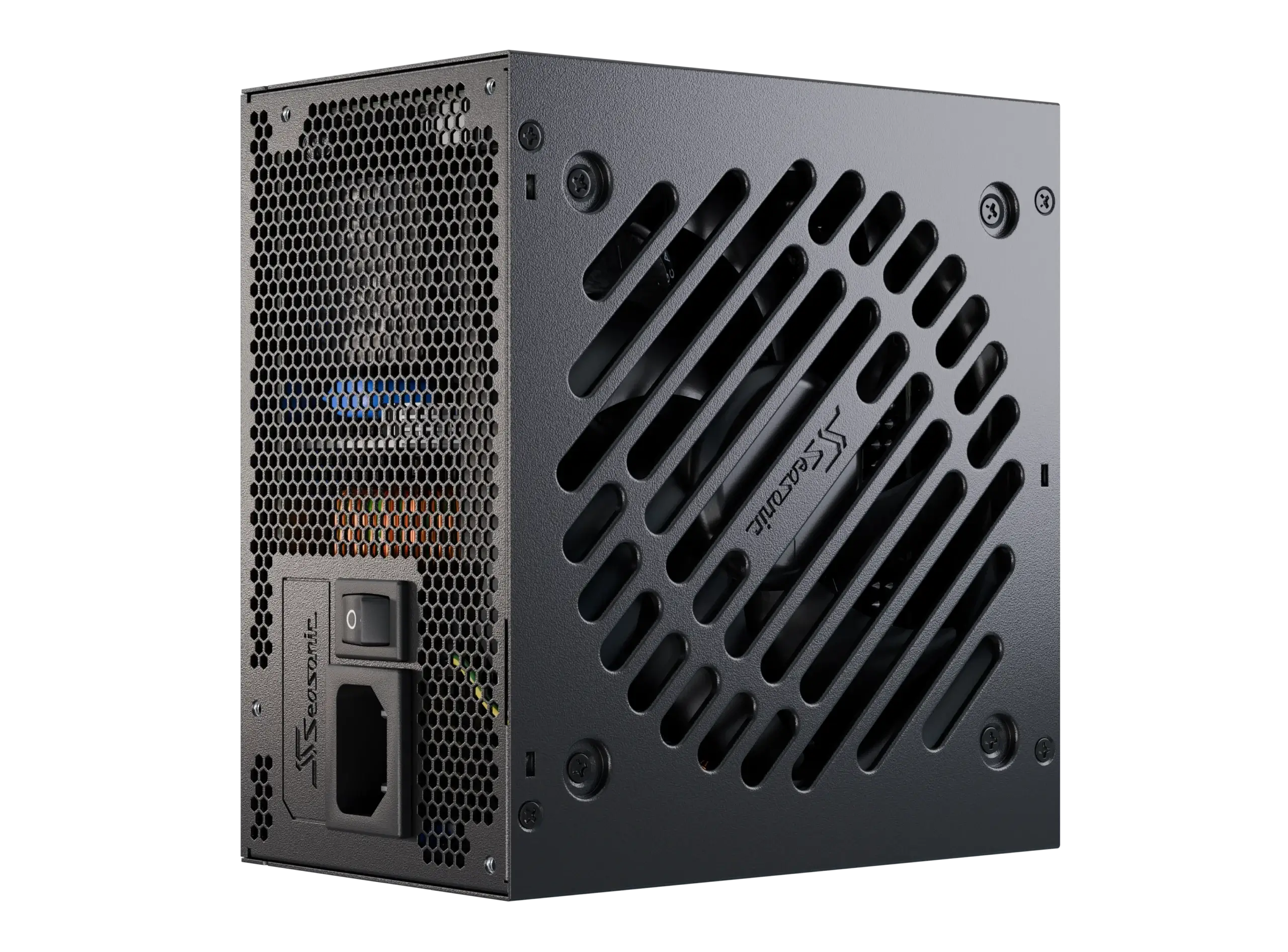
FOCUS PX ATX 3.1 Series
The Renewed Center of Attraction
Power Supplies
PRIME TX ATX 3.1 is the Best PSU 2026
Seasonic at Computex 2026
Highlights from Taipei
Accessories
Seasonic Native 12VHPWR 90° Cable
Accessories
Seasonic Native 12V-2×6 Cable
Power Supplies
FOCUS PX ATX 3.1 Series
FOCUS GX-1000 ATX 3.1


Het is een betrouwbaar ontwerp dat al jarenlang constant wordt geoptimaliseerd. In ruil daarvoor krijg je namelijk ook een garantieperiode van 10 jaar en een compact ontwerp met veel airflow.
Read More
TechGaming

PRIME TX-1600 ATX 3.1

A full array of 105C rated Japanese capacitors is a premium Im always happy to pay for.
Read More
eTeknix
PRIME PX-1600 ATX 3.1

Terminamos la Review de la Seasonic Prime PX-1600W ATX 3.1 PCIe 5.1 destacando que tenemos una fuente de alimentación Premiun de alto Rendimiento, al igual que sus hermanos Titanium maneja muy bien la carga de trabajo sin problema.
Read More
MasterBitz Review
CORE GX-850 ATX 3.1

De Seasonic Core GX verdient wat ons betreft een Excellent Award.
Read More
Technology Insider
PRIME PX-2200 ATX 3.1

There is no question that the Seasonic Prime PX-2200 fully earns its flagship status. As Seasonics own top-tier design, the overall execution is exactly what we would expect from one of the most respected PSU manufacturers in the industry, with excellent build quality and robust power delivery throughout our testing.
Read More
Kitguru
PRIME TX-1300 ATX 3.1


Terminamos la Review de la Seasonic Prime TX-1300W ATX 3.1 PCIe 5.1 destacando que tenemos una fuente de alimentación Premiun de alto Rendimiento, al igual que su hermano mayor maneja muy bien la carga de trabajo sin problema.
Read More
MasterBitz

PRIME TX-1300 ATX 3.1

Für Enthusiasten, die Wert auf Leistung, Effizienz und leisen Betrieb legen, ist das Seasonic Prime TX-1300 eine ausgezeichnete Wahl.
Read More
HardwareInside.de
PRIME TX-1300 ATX 3.1

Avec sa Prime TX-1300 ATX 3.1, Seasonic arrive a décrocher la première place de nôtre comparatif de peu.
Read More
Overclocking.com
FOCUS GX-1000 ATX 3.1
Pour conclure, la Seasonic Focus GX-1000W est sans grande surprise une alimentation de très bonne facture.
Read More
Overclocking.com
PRIME TX-1600 ATX 3.1

Seasonic ofrece calidad de rendimiento y construcción cumpliendo a cabalidad el estándar ATX 12V 3.1 sin problema con una garantía de 12 años para la serie Prime.
Read More
MasterBitz


Wattage Calculator
Calculate how much power your system needs by entering your setup

1CPU Information

2GPU Information

3Peripherals Information

4Form Factor

5Results
Product Warranty
The product does not perform as expected? Check if you are eligible for a warranty claim here.
Explore all
FAQ and Troubleshooting
Having problem with installation or configuration? A lot of the typical issues are covered in the knowledge database.
Explore all
Where to Buy
Find the local retailer for Seasonic products and get your PC upgrade now!
Explore all
Register your device and have chance
to win a $50 Steam Card
Welcome to the Seasonic Steam Card Giveaway! To show our appreciation that you have purchased our product we have launched a Steam Card Giveaway.